


Authors: F. Albarracin, M. Meriac
Modern conductive fabrics exhibit interesting properties for low-cost shielding applications. Lightning protections and low-cost covers for mobile phones are great examples of the proposed applications. Given the flexibility and modest costs attached, the fabrics could be of higher interest if their post-processing could lead to new applications. In this short technical paper, we explain the manufacturing process of conductive fabrics that can create Frequency Selective Surfaces (FSS).
A. Introduction - Frequency Selective Surfaces
Frequency Selective Surfaces refer to the arrangement of electrically small resonating unit-cells that exhibit filtering, absorbing or polarising properties when illuminated by electromagnetic waves [1], [2]. The manufacturing processes of FSS structures on hard and soft materials have been reported in several papers [2], [3]. However, the time of manufacturing and their costs remain challenging, especially when considering iterative processes and quick prototyping. Finding a simple and fast manufacturing methodology would enable an agile and fast method of producing and testing FSS for different applications. Furthermore, performing such processes at low costs and with readily available material could significantly drive down the overheads and ensure sustainable innovation.
One of the more well-known FSS arrangements comprising Split Ring Resonators (SRR) and its complementary version - Complementary Split Ring Resonators (CSRR), have been studied closely during the last several years as compact structures for FSS applications [4]–[6]. Unit cell size and separation between the cells must be significantly smaller than the wavelength of the impinging waves [4]. An important characteristic of these resonators is the capability they hold of cross polarisation - making them eminently suitable for radomes and stealth coating applications, for example. In [6], the authors proposed a flowchart for the design of FSS for filtering the wave radiated from High-Power Electromagnetic (HPEM) sources. We propose hereafter to investigate the possibility of manufacturing the FSS structures presented in [6] on low-cost, flexible conductive fabrics.
B. Laser-based manufacturing of FSS
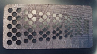
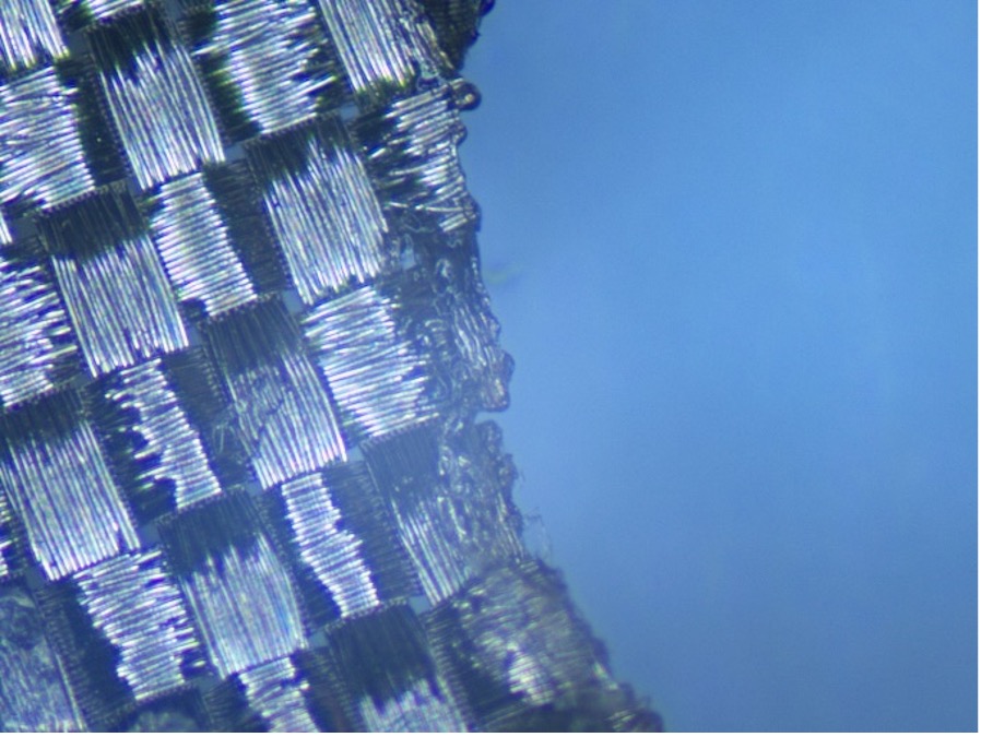
Figure 1, a fabric sample with lasered holes ranging from 3mm to 1.2mm can be seen - with holes reducing in size in decrements of 10%. We used a commercial CO2 laser (Universal VLS4.60, 60 Watt, 10.6 μm) in etching mode to create the FSS structures. The fabric started breaking between 1.5mm hole sizes at the bridges due to charring and disruption of the weaving pattern. Thanks to the conductive fabric's synthetic fibres, the laser-induced thermal fusing of the cuts prevented them from fraying. A microscopic view of the thermally fused yarns is shown Figure 2.
To improve the handling and resilience of the conductive fabric, we backed it with adhesive liners before starting the laser process. We had good results using temporary adhesive liners (adhesive Kraft paper) for stiffening the thin fabric during laser processing. However, through using a more advanced laser system with a vacuum bed and a laser-cut fixture, we could avoid the temporary adhesive liners for self-supporting FSS structures whenever stiffening of the fabric was required during laser processing.
We tested permanent thick cotton liners and synthetic fabrics as backing materials. When non-conductive linen was used, laser-etching to create arbitrary shaped FSS structures in the conductive fabric layer becomes possible. Having the non-conductive liner enables us to selectively evaporate only the conductive fabric - while leaving the liner fabric intact as mechanical support. The backing liner, therefore, prevents damage of the FSS when removing the finished FSS fabric from the laser bed - through maintaining the relative alignment of the FSS structure.
By adding a second hot-melt liner fabric as a backing after the laser etching process, we further strengthen the FSS structure to increase its mechanical resilience. The hot-melt liner is based on polyester and has usually a thin hot-melt coating similar to the material used in hot glue sticks (Ethylene Vinyl Acetate or EVA). By using a manual clothing iron or an industrial feed ironing machine, the hot-melt coating is heated to its melting point. By applying pressure and heat to the adhesive liner, the liner fuses to the back of the FSS conductive fabric – holding the FSS structures in place and preventing movement of them during deployment. The combination of liner and fused hot-melt layer also stiffens the fragile FSS structure.
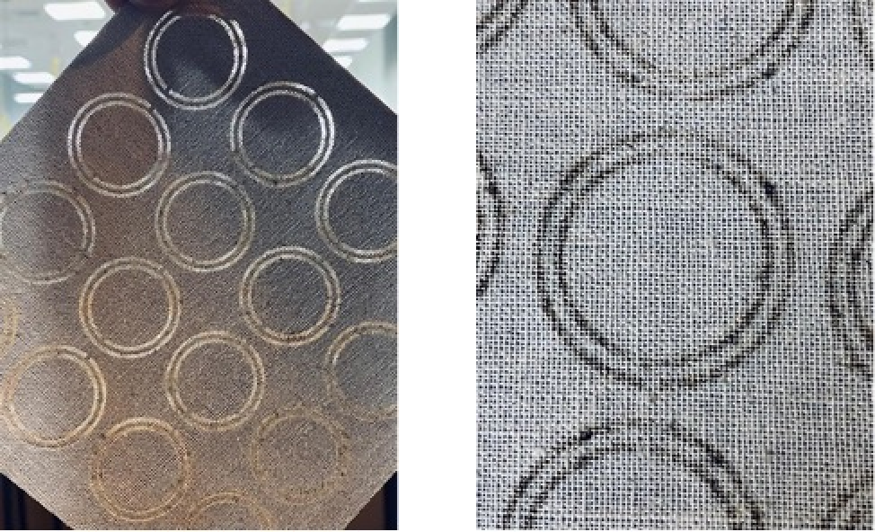
Figure 3 CSRR unit cells etched out the conductive fabric. Hot-melt linen is added for stiffening
On a final step, we used the laser-etching instead of laser-cutting function. Instead of cutting out the fabric and removing the cut-outs manually, we reduced the power and adjust the duration of the laser pulse, so the laser evaporates only metal layer and leaves in place the background fabric. As extracting the cut-outs is not required, the resulting structure has higher quality -as we avoid unintentionally damaging the fabric while removing the cut-outs. The results are worth the extra time required by the laser-etching process, which is considerably longer than the typical laser-cutting. Manufactured CSRR unit cells out of the conductive fabric are shown Figures 3a and 3b.
C. Experimental Electromagnetic Validation
One section of eight CSRR unit-cells, initially designed to pass a band around 1.5 GHz [6], was etched out from conductive fabric and tested in a waveguide setup (WR650 standard) for transmission-reflection characterisation, as shown in Figure 4(a). The complete hollow transversal section of the WR650 waveguide was sealed with copper tape to avoid any resonant aperture inside the cavity. A section of untreated conductive fabric was tested in the same way, as a benchmark to check the expected conductive behavior of the fabric. A two-port S-parameters measurement setup was calibrated as shown in Figure 4(b).
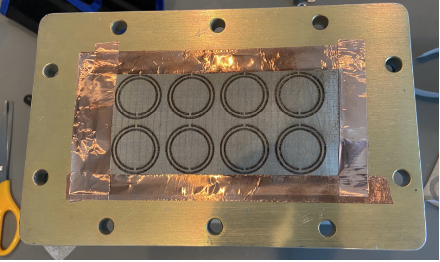
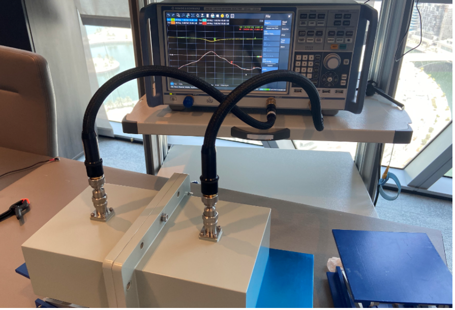
Figure 4 (a) WR650 waveguide section with an 8-unit CSRR bandpass FSS sample. (b) Measurement setup
The results are presented in Figure 5 as the scattering (S) parameters of the waveguide setup. S11 and S21 parameters represent the reflection and the transmission response, respectively. The untreated fabric wall shows sufficiently high insolation between port-1 and port-2, as seen in Figure 5(a), as the S12,21<-70 dB, and S11.22 ≈ 0 dB across the measured band. This verifies the high conductivity property of the fabric. Figure 5 shows the transmission-reflection parameters of the FSS section, including the simulated ones from CST® software suite. For a passband FSS, one should expect a low S11 parameter (highly negative value in dB), and a high S21 (close to 0 dB as possible). Measured results agreed well with the simulation. The non-perfect filtering response can be attributed to the non-zero metallisation thickness and the losses in the FSS, associated with the conductor and the stiffening linen.
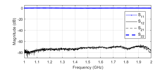
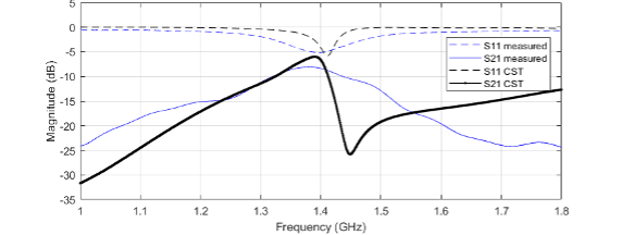
Figure 5 (a) Measured S-parameters of a untreated conductive fabric-wall. High insolation between port-1 and port-2 is observed. (b) S-parameters of the 8-cells sample, comparing simulation and measurement.
D. Conclusion and Future Work
An alternative fabrication process for FSS arrangements based on conductive fabric has been presented. The strength of the presented technique relies on readily available conductive fabrics and laser cutter machines. Commercial laser cutters, working in the etching mode, are used to engrave the unit-cells composing the FSS. A sample of a band-pass FSS, based on eight complementary split ring resonator (CSRR) unit-cells has been fabricated and tested to verify the effectiveness of the fabrication procedure and the viability of using conductive fabrics to implement resonant structures at the RF and microwave regime.
Innovative designs involving FSS-based structures are now enabled for quick prototyping and experimental characterisation across modern applications such as smart radomes, wearable antennas, smart clothes, and electromagnetic absorption covers, among others. We now aim to further investigate the combination of multiple FSS’s and dielectric layers for the above applications.
E. Acknowledgements
The authors would like to thank E. Neira, G. Appiah, F. Vega, N. Mora, C. Kasmi for their contribution to this work.
F. References
[1] B. A. Munk, Frequency Selective Surfaces: Theory and Design. New York: John Wiley & Sons, 2005.
[2] F. Costa, A. Monorchio, and G. Manara, “Analysis and Design of Ultra Thin Electromagnetic Absorbers Comprising Resistively Loaded High Impedance Surfaces,” IEEE Transactions on Antennas and Propagation, vol. 58, no. 5, pp. 1551–1558, May 2010, doi: 10.1109/TAP.2010.2044329.
[3] J. D. Ortiz, J. D. Baena, V. Losada, F. Medina, and J. L. Araque, “Spatial Angular Filtering by FSSs Made of Chains of Interconnected SRRs and CSRRs,” IEEE Microwave and Wireless Components Letters, vol. 23, no. 9, pp. 477–479, Sep. 2013, doi: 10.1109/LMWC.2013.2274997.
[4] R. Marqués et al., “Ab initio analysis of frequency selective surfaces based on conventional and complementary split ring resonators,” J. Opt. A: Pure Appl. Opt., vol. 7, no. 2, pp. S38–S43, Jan. 2005, doi: 10.1088/1464-4258/7/2/005.
[5] J. D. Baena et al., “Equivalent-circuit models for split-ring resonators and complementary split-ring resonators coupled to planar transmission lines,” IEEE Transactions on Microwave Theory and Techniques, vol. 53, no. 4, pp. 1451–1461, Apr. 2005, doi: 10.1109/TMTT.2005.845211.
[6] F. Albarracin-Vargas, F. Vega, C. Kasmi, D. Martinez, and L. O. Fichte, “Enhanced integrated multiband HPM radiator, combining a hyperband source with a high-Q frequency selective surface,” Comptes Rendus. Physique, vol. 22, no. S1, pp. 73–82, 2021, doi: 10.5802/crphys.63.